Všechny piny mají interní nastavitelný pull-up/pull-down rezistor, kromě 46 (fixní pulldown).
Všechny piny jsou obousměrné, kromě 46 (jen input).
The absolute maximum current drawn per GPIO is 40mA according to the “Recommended Operating Conditions” section in the ESP32-S2 datasheet.
| pin | funkce | omezení |
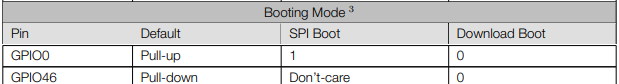
| 0 | PWM | boot mode selection |
| 1 | TOUCH1, ADC1_CH0, RTC GPIO, PWM | |
| 2 | TOUCH2, ADC1_CH1, RTC GPIO, PWM | |
| 3 | TOUCH3, ADC1_CH2, RTC GPIO, PWM | |
| 4 | TOUCH4, ADC1_CH3, RTC GPIO, PWM | |
| 5 | TOUCH5, ADC1_CH4, RTC GPIO, PWM | |
| 6 | TOUCH6, ADC1_CH5, RTC GPIO, PWM | |
| 7 | TOUCH7, ADC1_CH6, RTC GPIO, PWM | |
| 8 | TOUCH8, ADC1_CH7, RTC GPIO, PWM | |
| 9 | TOUCH9, ADC1_CH8, RTC GPIO, PWM | |
| 10 | TOUCH10, ADC1_CH9, RTC GPIO, PWM | |
| 11 | TOUCH11, ADC2_CH0, RTC GPIO, PWM | |
| 12 | TOUCH12, ADC2_CH1, RTC GPIO, PWM | |
| 13 | TOUCH13, ADC2_CH2, RTC GPIO, PWM | |
| 14 | TOUCH14, ADC2_CH3, RTC GPIO, PWM | |
| 15 | U0RTS, ADC2_CH4, (krystal 32 kHz p), RTC GPIO, PWM | |
| 16 | U0CTS, ADC2_CH5, (krystal 32 kHz n), RTC GPIO, PWM | |
| 17 | U1TXD, ADC2_CH6, DAC_1, RTC GPIO, PWM | |
| 18 | U1RXD, ADC2_CH7, DAC_2, RTC GPIO, PWM | |
| 19 | U1RTS, ADC2_CH8, USB_D-, RTC GPIO, PWM | native USB |
| 20 | U1CTS, ADC2_CH9, USB_D+, RTC GPIO, PWM | native USB |
| 21 | RTC GPIO, PWM | |
| 26 | SPICS1, PWM | PSRAM, FLASH |
| 27 | SPIHD | PSRAM, FLASH |
| 28 | SPIWP | PSRAM, FLASH |
| 29 | SPICS0 | PSRAM, FLASH |
| 30 | SPICLK | PSRAM, FLASH |
| 31 | SPIQ | PSRAM, FLASH |
| 32 | SPID | PSRAM, FLASH |
| 33 | SPIIO4, FSPIHD, PWM | |
| 34 | SPIIO5, FSPICS0, PWM | |
| 35 | SPIIO6, FSPID, PWM | |
| 36 | SPIIO7, FSPICLK, PWM | |
| 37 | SPIDQS, FSPIQ, PWM | |
| 38 | FSPIWP, PWM | |
| 39 | MTCK, PWM | JTAG |
| 40 | MTDO, PWM | JTAG |
| 41 | MTDI, PWM | JTAG |
| 42 | MTMS, PWM | JTAG |
| 43 | U0TXD | |
| 44 | U0RXD | |
| 45 | flash+spiram Vcc select | |
| 46 | boot mode selection pouze vstupní | |
The ESP32-S2 chip features hardware filters to remove unwanted glitch pulses from the input GPIO, which can help reduce false triggering of the interrupt and prevent a noise being routed to the peripheral side. Each GPIO can be configured with a glitch filter, which can be used to filter out pulses shorter than two sample clock cycles. The duration of the filter is not configurable. The glitch filter is disabled by default, and can be enabled by calling gpio_glitch_filter_enable().
Possible PWM GPIO pins on the ESP32-S2: 0,1-17,18,19-21,26,33-42
